 Many utilities and industries around the world were holding their breath for many years for publication of the new Arc-flash calculation guide. At the end of 2018, the Institute of Electrical and Electronics Engineers (IEEE) voted and approved a new Arc-Flash calculation methodology that can be used to assess incident energy for three-phase, line-to-line, voltages between 208V and 15,000V. Calculations for single-phase AC systems and DC systems are not part of the standard but it does offer some guidance and references for those applications. Incident energy is the amount of thermal energy generated during an electric arcing event at any discrete distance from the source. It is extremely important to know these values to be able to equip electrical workers with the proper personal protective equipment (PPE). Changes in the calculation methodology can impact these values which could alter the level of PPE required or even require work to be done de-energized.
IEEE 1584-2002 vs IEEE 1584-2018…What Changed?
 The new methodology completely overhauls the exposure energy calculation methodology and significantly complicates the analysis, although it does provide more granularity based on the inputs. The new method uses an iterative approach and many coefficients to find the final incident energy. As with the old method: fault current, clear time, gap and approach distance still play a major role in the incident energy calculation. Extensive arc-flash testing by IEEE in collaboration with NFPA determined that the orientation of the electrodes (live parts) has a considerable effect on the incident energy. 1584-2002 claimed that there was no distinction between open and box configurations for high voltage faults. Arc-flash tests prior to the 2018 version of the standard concluded that the plasma cloud ejected by the arc has liquid properties, and that both the electrode configuration and confinement in a box will impact plasma movement and dissipation. The horizontal electrode arrangement will yield higher incident energy as the plasma cloud and arc will be expelled horizontally towards the electric worker. While in vertical electrode configuration the plasma cloud and arc will be expelled parallel to electrodes. Thus, incident energy exposure will be affected by the worker’s location relative to the vertical electrodes. The general direction of plasma cloud is determined by the ends of the electrodes in relation to the worker.
The box cases of both configurations have a higher incident energy than their open-air counterparts, as the “box” will cause the plasma cloud to be more concentrated. The plasma cloud of an open-air case would dissipate faster, thus reducing the incident energy.
What determines the electrode configuration?
The configuration of the bus and conductor primarily determine the electrode configuration. Any overhead pole with equipment can have multiple configurations. The key is to be able to identify the configuration when performing work. If electrical terminators, such as spade terminals, are configured such that they are perpendicular to the worker, the configuration will be horizontal. If electrical terminators are configured such that they are parallel to the worker, such as terminators on a riser pole, the configuration will be vertical.
The box or open-air component is determined if the electrodes are partially enclosed. Most open-air cases are apparent when working on overhead power lines and pole mounted equipment such as transformers and reclosers. The terminations in these cases are not surrounded by barriers. Most closed box cases are apparent when working on meters and pad-mounted equipment as the electrodes will typically be surrounded by the walls of the equipment.
What about changes involving enclosed box work?
The concept of enclosed “box” work isn’t unique to the 2018 methodology, as the 2002 method addresses it. The old approach used two sets of coefficients to distinguish between the open air and enclosed box calculations. The 2018 method also uses sets of coefficients distinguishing between open air and enclosed box calculations. The major change with the IEEE 1584-2018 is the inclusion of the equipment box’s dimension size and determining if the box is “typical” or “shallow”. This would require obtaining the length (depth), width and height of any pad-mounted equipment or meter boxes to perform the 2018 calculations. The incident energy values will also be different depending on if the box is shallow or typical. For the most part, any enclosed distribution equipment will be “typical”, however, if all the following criteria are met, the box will be considered “shallow”: 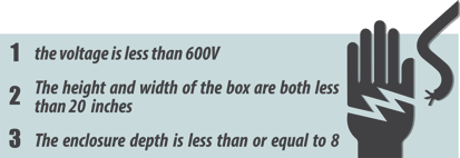
These additions to the standard can result in slightly different incident energies for different equipment, such as pad-mounted transformers and junction cabinets, at the same location having the same fault current.
What are the impacts of the changes in IEEE 1584?
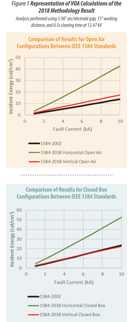 Using the new equations, higher incident energy levels are expected. The charts below show the comparison of the IEEE 1584-2002 method to the IEEE 1584-2018 method for both open air and closed box cases.
Figure 1 shows the vertical electrode configuration (VOA) calculations of the 2018 methodology result in similar incident energies that are slightly higher than 2002 methodology at 4,000 amps of fault current. That is in sharp contrast to the horizontal electrode configuration (HOA) results that have roughly 200% higher incident
energies at 4,000 amps of fault current. This would require workers to wear higher calorie clothing, where a 4 calorie or 8 calorie clothing system would have sufficed under the old methodology.
How Do We Mitigate Exposure?
Since the calculated incident energies are higher under the new methodology, electric utilities may want to consider strategies to reduce incident energy exposure to line personnel. First and foremost, the safest way to work on a system without the threat of arc-flash is to work de-energized. Working a system de-energized eliminates the possibility of an arc-flash related incident. If work can’t be performed de-energized, reducing the time duration of the fault can reduce the incident energy. A common method is to utilize hot-line tags (HLT) that implement near instantaneous tripping on electronic reclosers that result in clearing times of 5-10 cycles. This reduction can greatly reduce the incident energy. An added benefit when using HLT is that a worker downline is protected from multiple recloser operations. If the upline device is not capable of using HLT, then use of the non-reclose function is recommended. This would default to tripping on the first curve of the device’s operation sequence. With this option, the clearing time is dependent on the curve used in the device for coordination. If a utility primarily uses delay curves for feeder protection, an alternate “maintenance” profile should be considered where a faster curve can be implemented in conjunction with the non-reclose feature to reduce incident energy. Another way to decrease incident energy is to increase the working distance from the arc. This can be achieved by utilizing live-line tools.
Final Thoughts
Appendix E to Subpart V of Part 1926 discusses the need for electric industry employers to assess the workplace for electric-arc hazards. The document provides acceptable methods for the calculation which includes IEEE 1584-2002 and the 2017 NESC. Since OSHA specifically does not endorse any methodology, it is the onus of the employer to determine the incident energy and the new IEEE 1584-2018 may be the tool to use.
For more information or to comment on this article, please contact:
![]() Curtis Freeman, Project Consultant | CONTACT
Curtis Freeman, Project Consultant | CONTACT
GDS Associates, Inc. – Marietta, GA
770-799-2362 or curtis.freeman@gdsassociates.com